igusigus-icon-cart(0)

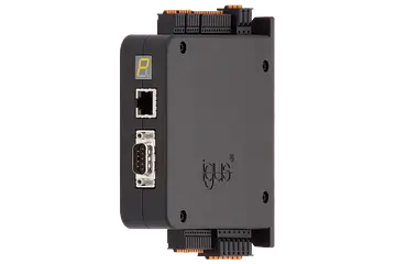
drylin® D1 motor control system for stepper, DC and EC/BLDC motors

D1 product image
igus-icon-lupe
<p>1. Power supply: logic and load supply are separate in order to enable safety shutdown. Logic supply is 12-24V and load supply is 12-48V.<br><br>2. Digital inputs: movements can be selected, started and stopped at the 10 predefined inputs. With two limit switches and a release input, the motor control system can also assume safety functions.<br><br>3. Digital outputs: information from the motor control system can be called up at the 5 predefined outputs. The motor control system reports whether it is ready or is currently executing a movement, whether it is referenced or whether there are warnings or errors.<br><br>4. Analogue inputs: two analogue inputs can be used to read absolute position information from a linear axis, for example, or to specify speeds or positions. A linear axis can be moved using an &quot;electronic hand wheel&quot; without having to change the parameters.<br></p>
igus-icon-lupe
5. Angular encoder: in order to enable optimum motor control and specification of an exact position, an angular encoder is needed. The motor control system is designed for many different encoder types with a power supply of 5V.

6. Motor &amp; brake connection: the motor connection is suitable for DC, 3-phase EC and 2-phase stepper motors. A motor brake connection is also integrated in this connector.
igus-icon-lupe
7. CANopen: the CANopen connection is a communication protocol used to communicate with higher-level control systems. It is used for the control system of individual axes, but primarily to operate multi-axis systems. drylin® E flat, line or room linear robots can be optimally operated with CANopen.

8. Ethernet: the Ethernet port is used to call up the graphic user interface via a browser or to communicate via Modbus TCP.

9. Display: the LED status display provides information on the IP address or on the status of the control systems. For example, it independently outputs the IP address of the motor control system or displays warnings or error messages.
igus-icon-lupe
D1 technical drawing
igus-icon-lupe
play iconD1 video
igus-icon-lupe
play iconD1 video
igus-icon-lupe
1 of 7
drylin® D1 motor control system for stepper, DC and EC/BLDC motors
<p>1. Power supply: logic and load supply are separate in order to enable safety shutdown. Logic supply is 12-24V and load supply is 12-48V.<br><br>2. Digital inputs: movements can be selected, started and stopped at the 10 predefined inputs. With two limit switches and a release input, the motor control system can also assume safety functions.<br><br>3. Digital outputs: information from the motor control system can be called up at the 5 predefined outputs. The motor control system reports whether it is ready or is currently executing a movement, whether it is referenced or whether there are warnings or errors.<br><br>4. Analogue inputs: two analogue inputs can be used to read absolute position information from a linear axis, for example, or to specify speeds or positions. A linear axis can be moved using an &quot;electronic hand wheel&quot; without having to change the parameters.<br></p>
5. Angular encoder: in order to enable optimum motor control and specification of an exact position, an angular encoder is needed. The motor control system is designed for many different encoder types with a power supply of 5V.

6. Motor &amp; brake connection: the motor connection is suitable for DC, 3-phase EC and 2-phase stepper motors. A motor brake connection is also integrated in this connector.
7. CANopen: the CANopen connection is a communication protocol used to communicate with higher-level control systems. It is used for the control system of individual axes, but primarily to operate multi-axis systems. drylin® E flat, line or room linear robots can be optimally operated with CANopen.

8. Ethernet: the Ethernet port is used to call up the graphic user interface via a browser or to communicate via Modbus TCP.

9. Display: the LED status display provides information on the IP address or on the status of the control systems. For example, it independently outputs the IP address of the motor control system or displays warnings or error messages.
drylin® D1 motor control system for stepper, DC and EC/BLDC motors
igus-icon-arrow-left
igus-icon-arrow-right
  • For single axes, line, flat, linear and room linear robots and delta robots
  • No software installation or app required
  • Use with PC, tablet or smart phone
  • Stepper (ST), DC and EC/BLDC motors with up to 21A peak currents and 48V
  • Digital inputs/outputs, analogue inputs, CANopen, ModbusTCP (CANopen gateway) for connection to master control systems, e.g. Siemens or Beckhoff
  • Matching sample programs
Item no.
InfoInfoigus-icon-infoYOU CAN DOWNLOAD THE APPROPRIATE SAMPLE PRODUCT RANGE HERE FOR FREE.

Consulting

I would be happy to answer your questions personally

Ong Liang You (Ryan)

igus-icon-phone+65 9642 2939

Shipping and consultation

In person:
Monday to Friday from 8am - 8pm.
Online:
Chat service
24h